
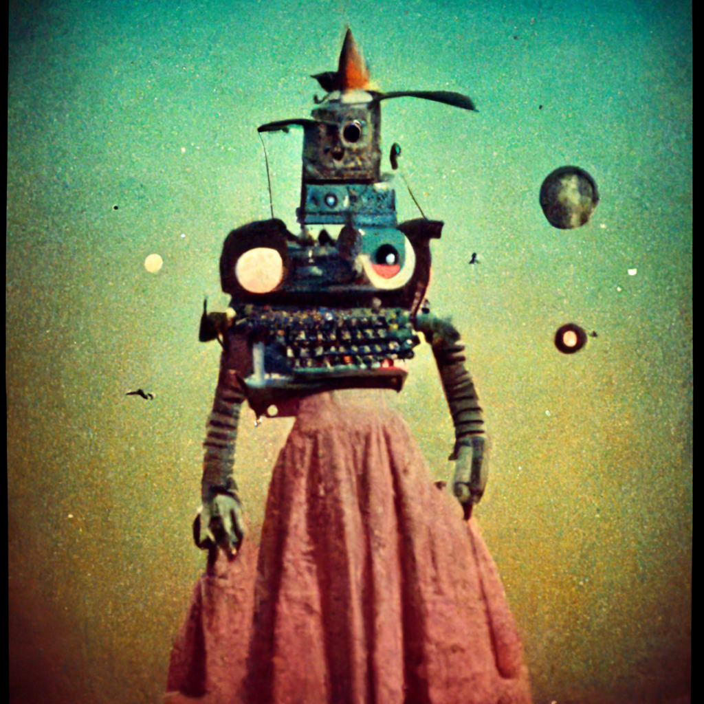
!!! techn010ffspring !!! [v.9] named [frances-nannie-ella-clothes-mangles-protector-stenographer-breast-piece-contrivance-for-the-comibnation-of-a-watch-dial-and-hands-moisture-removal-rotary-multicopy]

Interactive Game
Coming Soon
C & P TELEPHONE CO. SWITCHBOARDS
[H1] C & P Telephone C. Switchboards ● Black and White Photograph ● 1905 ● Harris & Ewing photograph collection ● Library of Congress Website 2016861597
Library of Congress. ● Link to Image: https://www.loc.gov/resource/hec.20543/

tingling typewriter computer bite hold squirrel sister sun ear wax cake sue williams family room Margaret e knight (1838-1914) identical twins neck smoosh flummoxed
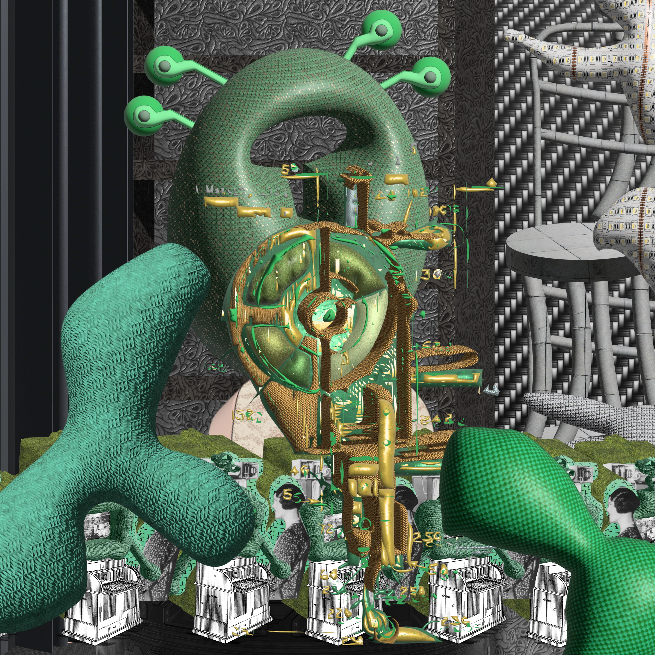
[F1], [B17], [C17] Images made using nonsensical prompts that are output from my !!! techn010ffspring !!! idea generator and then input as absurd combinations of words for AI Midjourney Image Generator to grapple with, in order to confound the AI in a refusal of its training, or an absurdity-detraining.
This image was made using the AI Art Generator Midjourney by entering the prompt created by my !!! techn010ffspring !!! idea generator.
The idea generator can be found at the link: https://openprocessing.org/sketch/1635641
The prompt entered was: “tingling typewriter computer bite hold squirrel sister sun ear wax cake sue williams family room Margaret e knight (1838-1914) identical twins neck smoosh flummoxed”
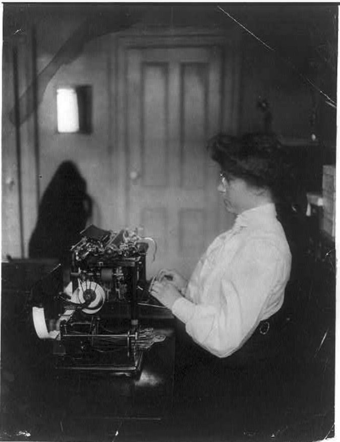
[Woman typist]. 1900.
[E17] “[Woman typist]” ● Black and White Photograph ● 1900 ● Library of Congress Website 2013647253 ● “Photograph shows woman seated at desk using stenograph.”
Library of Congress. ● https://www.loc.gov/item/2013647253/

Semele Short. ● Patent No. 145,910. ● 1873. ● Improvement in clothes-mangles.
[A1] Semele Short ● Patent #US145910A ● Patented December 23, 1873 ● “Clothes-Mangles” ● “While thus especially applicable for use on larger articles, such as are liable to lose their proper shape in the laundry, it is evident my apparatus may also be used with great advantage on almost every description of clothing or linen.
I claim as new and of my invention- The mangle constructed, as herein described, with clamp-rolls B B, metallic cylinders E E, heaters N N, springs F F, caps H H, idlers I J J, and springs P, the whole mounted in a suitable frame and driven by suitable gearing, in manner substantially as and for the purpose set forth.”
SEMELE snon’r, or CINCINNATI, OHIO.
“IMPROVEMENT IN CLOTHES-MANGLES.
Specification forming part of Letters Patent No. 145,910., dated December 1873; application filed December 10, 1873.
. cept those having very unequal thicknesses or possessing brittle projections, such as buttons, &c.
Figure 1 is a perspective view of a mangle embodying my improvements. Fig. 2 is a transverse section thereof. Fig. 3 is an enlarged transverse section of one of the clamping-rolls.
Journaled horizontally in a suitable frame, A, are two wooden clamping-rolls, B B, which terminate outside of the frame in spur-wheels G O, which gear with a corresponding cogwheel, D, on the end of a hollow metallic cylinder, E. E is another precisely similar cylinder, which is caused to press down upon the one E by the action of springs F F, whose stress is capable of being increased, at will, through the instrumentality of screws G G G G and caps H H. Arms I I, pivoted to the frame, carry at their free extremities wooden idlers J J, which, resting upon the cloth or goods being operated upon, act to take up the slack of said goods, and to keep it properly on the stretch. These idlers may be caused to press down upon the goods with any degree of force by india-rubber bands 1?, which engage over the arms I, and under the brackets .to which said arms are pivoted. These arms may be provided with spurs or notches to retain the bands in proper position, or said bands may be omitted and metallic springs P substituted for them, as shown in Fig. 2. The clamping-rolls have each a longitudinal groove or channel, K, to receive a clamp, L, which, after the end of the goods has been introduced, is secured by means of screws M M. N N are iron heaters, which, having been raised to the proper temperature, are inserted in their respective cylinders, E E, in order to bring and maintain the same at that degree of heat which will efl’ectually smooth without injuring the goods. A winch,
O, on the end of the-cylinder E, enabl s the laundress to rotate the same, whence motion is communicated, as per arrows, to the rollers.
The operation of the machine is as follows: The heaters having been made sufficiently hot,
by being inserted in a fire, are then introduced ders E and E, and, having been clamped in the other roll, the crank is then rotated to and fro until the article is sufiiciently smoothed. Should the pressure of the upper cylinder E be found too great or too little, it can be regulated by means of the screws G G G G. The idlers J J effectually take up any slack which must otherwise arise from the changing diameters of the clamp-rolls, in consequence of the increase or decrease of goods upon them, in course of winding and unwinding. The ends of the goods being firmly caught in the clamp-rolls, it is impossible that the laundering should operate bias upon the goods, as in common mangling, or in smoothing by sadirons, and consequently the article, when finished, is found to possess its proper rectangular form, and not to be in any place unequally stretched.
While thus especially applicable for use on larger articles, such as are liable to lose their proper shape in the laundry, it is evident my apparatus may also be used with great advantage on almostevery description of clothing or linen.
I claim as new and of my invention- The mangle constructed, as herein described, with clamp-rolls B B, metallic cylinders E E, heaters N N, springs F F, caps H H, idlers I J J, and springs P, the whole mounted in a suitable frame and driven by suitable gearing, in manner substantially as and for the purpose set forth.
In testimony of which invention I hereunto set my hand. 7
SEMELE SHORT.”
Link to patent: patents.google.com/patent/US145910A
Semele Short. ● Patent No. 145,910. ● 1873. ● Improvement in clothes-mangles.
Semele Short. ● Patent No. 145,910. ● 1873. ● Improvement in clothes-mangles.
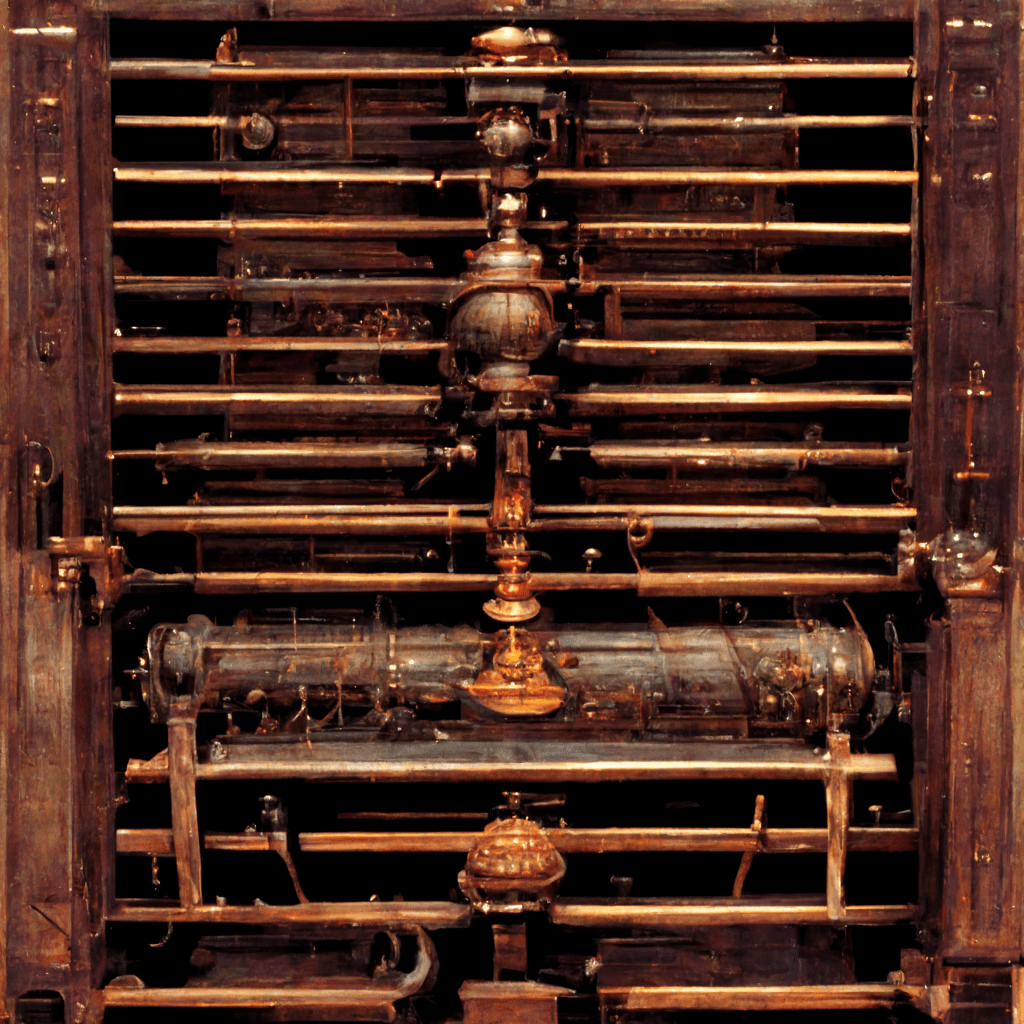
This image was made using Midjourney AI Art Generator with the prompt selected from text in the Patent No. 145,910 by Semele Short, from 1873, for an “Improvement in clothes-mangles”.
The prompt was “prompt: “I claim as new and of my invention- The mangle constructed, as herein described, with clamp-rolls B B, metallic cylinders E E, heaters N N, springs F F, caps H H, idlers I J J, and springs P, the whole mounted in a suitable frame and driven by suitable gearing, in manner substantially as and for the purpose set forth.”
Link to patent: patents.google.com/patent/US145910A

Semele Short. ● Patent No. 145,910. ● 1873. ● Improvement in clothes-mangles.
Semele Short. ● Patent No. 145,910. ● 1873. ● Improvement in clothes-mangles.
One of the textures in the background is a pattern made by an image generated by AI Art Generator Midjourney. The prompt was: “I claim as new and of my invention- The mangle constructed, as herein described, with clamp-rolls B B, metallic cylinders E E, heaters N N, springs F F, caps H H, idlers I J J, and springs P, the whole mounted in a suitable frame and driven by suitable gearing, in manner substantially as and for the purpose set forth.” which comes from the patent shown below by Semele Short for an “Improvement in Clothes-Mangles” from 1873. The patent elements are also part of the stand that the woman figure is supported by.
Link to patent: patents.google.com/patent/US145910A
AI for Illness Diagnosis.
[D1], [I17] Images made by AI Midjourney Image Generator using prompts that are the headlines of media articles that highlight gender-bias and issues related to Diversity, Equity, and Inclusion in STEM fields.
This image was made using Midjourney AI Art Generator with the prompt created using the title of the article with the same name:
Prompt: “Artificial intelligence could soon diagnose illness based on the sound of your voice”
Link to article: https://www.npr.org/2022/10/10/1127181418/ai-app-voice-diagnose-disease


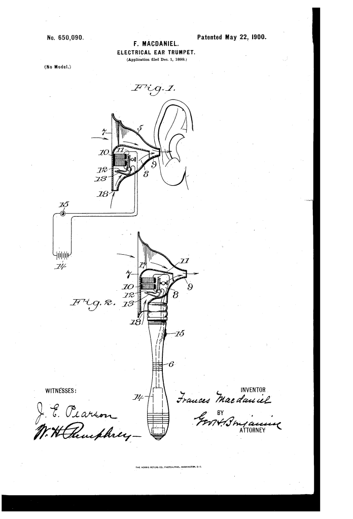
Frances MacDaniel. ● 1900. ● Patent No. 650,090. ● Electrical Ear Trumpet.
“Be it known that I, FRANCES MACDANIEL, a citizen of the United States, residing at New York city,county and State of New York,have invented certain new and useful Improvements in Electrical Ear-Trumpets, of which the following is a specification.
My invention is based upon the Well-known fact that many people commonly deaf to ordinary soundssuch, for instance, as the sounds of the human voice, music, or similar sounds of ordinary volume-can hear such sounds it produced in the presence of a sound of greater volume. Thus a person who cannot hear when spoken to in the quiet of an ordinary room will be able to hear whispers if taken into a factory and spoken to amid the many sounds due to the operation of machinery. Theoretically this condition is probably due to the influence of the ordinary sound-waves produced by the voice, music, or similar means acting as superposed waves or interfering waves with the influence created by the large sound-waves upon the nervecenters.
Myinvention is based uponthe above-stated fact and in its construction involves the principle of artificially creating near to the nervecenters sound-waves of determined tone and volume.
The mechanical construction of the instrument I prefer to be such that the sound-making apparatus shall be within the instrument and when in use brought into immediate proximity’to the ear and at the same time have the capacity for collecting and directing into the ear external sounds.
I do not limit myself in any wise to the mechanism for producing the sound-waves in the instrument. Preferably,however,the soundwaves will be created by the vibrations of a tuned reed set in motion by alternately making and breaking an electric circuit through a magnet.”
Link to Patent: https://patents.google.com/patent/US650090A
Pockets!
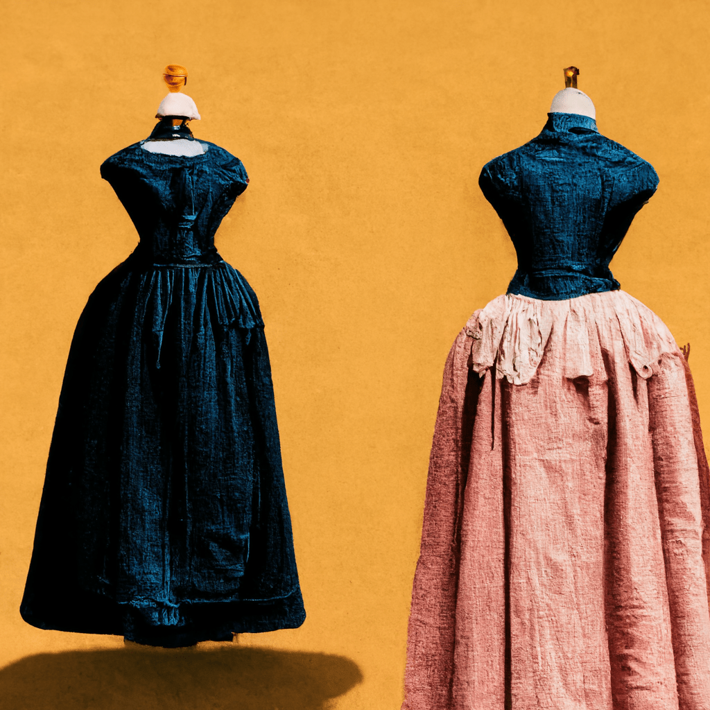
This image was made using Midjourney AI Art Generator with the prompt created using the title of the article with the same name:
Prompt: “A Pocket-Sized Dilemma for Women: Unlike men’s clothes, female fashion has been indifferent for centuries to creating ways for women to stash things in their garments”
Link to the article: https://www.wsj.com/articles/a-pocket-sized-dilemma-for-women-11664471344

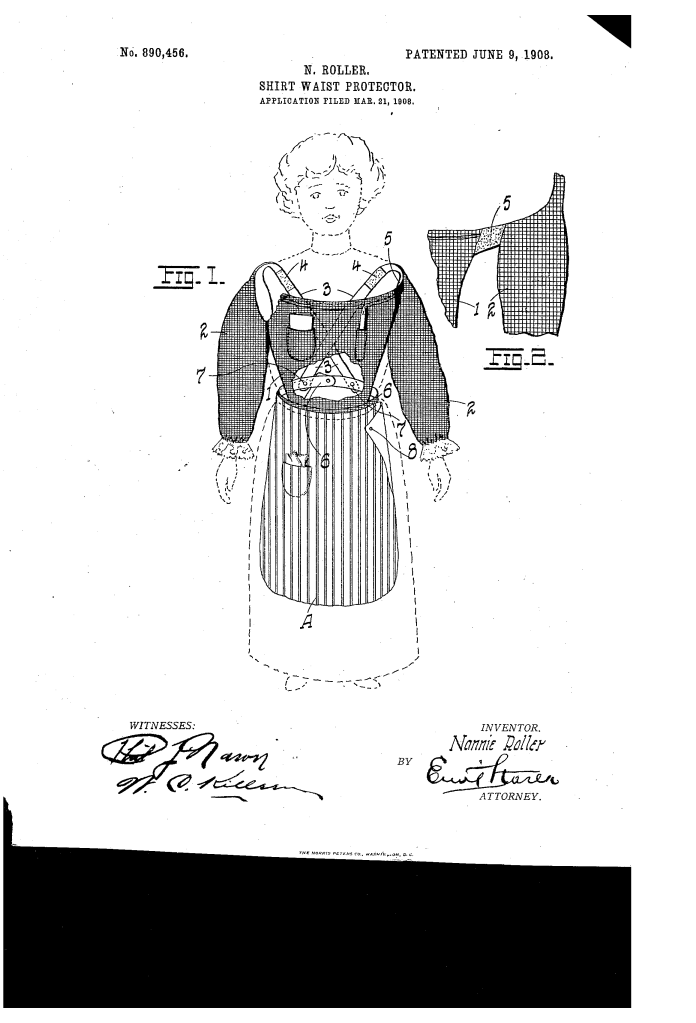
Nannie Roller. ● Patent 890,456. ● 1908. ● Shirt Waist Protector.
Nannie Roller. ● Patent 890,456. ● 1908. ● Shirt Waist Protector.
“The object of my invention is to provide a breast-piece which will protect the shirtwaist so commonly worn by women employees in the warm months of the year. Its advantages may be clearly apparent from a detailed description of the invention which. is as follows: V
Referring to the drawings, 1, represents a breast-piece provided with pockets and pencil holders if deemed necessary, as shown. The protector is equipped with a pair of sleeves, 2, 2 and has rear extensions or straps 3, 3 beyond the sleeves, the connection be tween the straps and sleeves being effected by strips of elastic sections 4, 4. Between the breast-piece and the sleeve arm-holes,”
Link: patents.google.com/patent/US890456A/
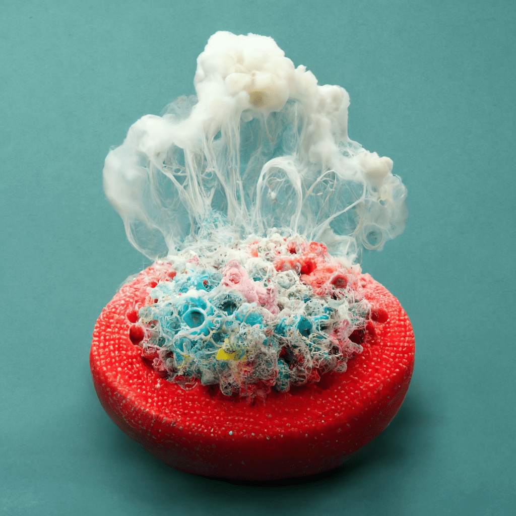
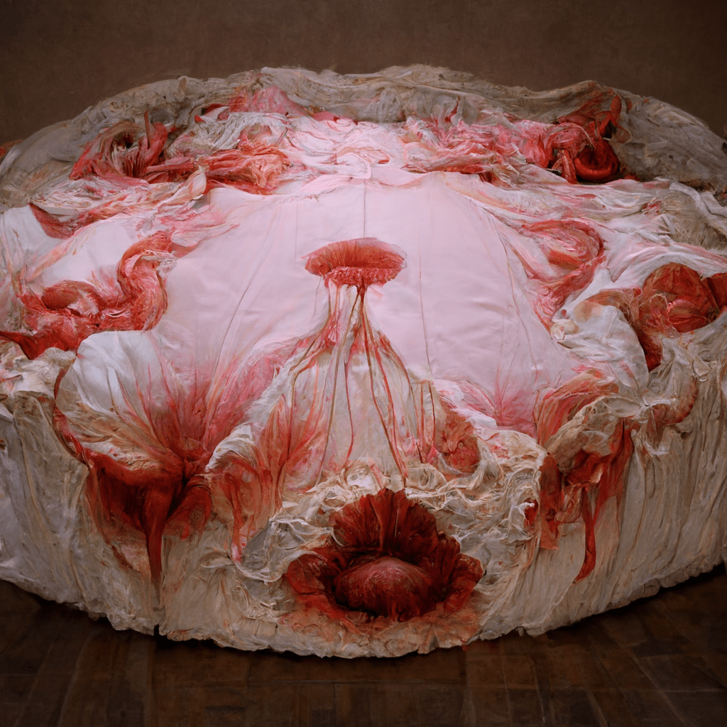
doris-with-cellular-sponge-material-reusable-tampon-exploding-bubbles
[F1], [B17], [C17] Images made using nonsensical prompts that are output from my !!! techn010ffspring !!! idea generator and then input as absurd combinations of words for AI Midjourney Image Generator to grapple with, in order to confound the AI in a refusal of its training, or an absurdity-detraining.
This image was made using Midjourney AI Art Generator with the prompt that is the name of one of the !!! techn010ffspring !!! :
Prompt: “doris-with-cellular-sponge-material-reusable-tampon-exploding-bubbles”
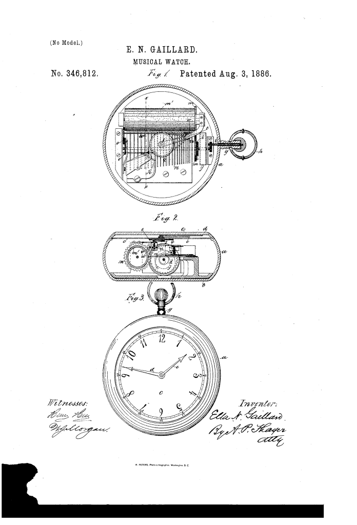
Ella N. Gaillard. ● 1885. ● Patent 346,812. ● Musical Watch.
[D17] Ella N. Gaillard ● Patent #US346812A ● Patented August 3, 1886 ● “Musical Watch” ● “My invention consists of an improved contrivance for the combination of a watch dial and hands with the mechanism of a music box, whereby the turning of the hands will be effected by the action of a mechanism for a simple and cheap imitation musical watch….making a simple device representing a musical watch for the amusement of children.”
“.Ee it known that I, ELLA N. GAILLARD, a citizen of the United States, residing at New York city, in the county and State of New York, have invented new and useful Improvements in Musical W’atches, of which the following is a specification.
My invention consists of an improved coir trivance for the combination of a watch dial and hands with the mechanism ofamusicbox, whereby the turning of the hands will be effected by the action of a inusictrain for a simple and cheap imitation musical watch, all as hereinafter fully described, reference being made to the accompanying drawings, in which Figure 1 is a plan view of the device with the dial and hands removed and the case and stem sectioned. Fig. 2 is a transverse section of the device on line :0 w, Fig. 1. Fig. 3 is a face view. I
I arrange the mechanism of a common music-box in a case, a I), resembling a watch-case, and having a watclrdial face, 0, and hands (Z 0, also having a hollow stem, and ring i2. and I fit the shaft i of the winding mechanism of the music apparatus through the hollow stem 1 in the manner of the winding-gear of astem-, winding watch.
To the music mechanism, which consists of the driving-spring j, ratchet 7;, driving-trnin in, pin-barrel m, comb 71, fan-driving train 0, and regulating-fanp, ofapproved contrivance, I gear the hands d 0 by means of a large pulley, g, and belt connected with the hour-hand and the small pulley s and belt connected with the minute-hand, which belts run on the short shaft 1, gearing by the worm-wheel a WATCH.
Serial No. 173,668. (No model.)
with the worm c on the shaft ’20, which gears with the train 0 of the fan-regulator with the powertrain m of the music apparatus, thus making a simple device representing a musical watch for the amusement of children.
For the belts I propose to employ flexible rubber bands, that will hug the pulleys and shaft, so as to avoid slipping, and at the same time will’be sufficiently light and flexible for the purpose.
The pulleys q and swill be suitably propou tioned for the required differential motions of the minute and hour hands.
I claim as my invention- 1. The improved combined musicbox and watch, consisting of the music apparatus inclosed in a watch-case having dial 0 and hands (Z c, the hands being differentially geared with the music-driving train by the shaft 2, bolts and pulleys g s, and the wornrgear a 2, substautially as described.
2. The improved combined music-box and watch, consisting of the music apparatus inclosed in a watclrcase having dial 0, hands d c, and hollow stem the windingshaft of the music mcclntnism being arranged in said hollow stem, and the hands being geared with the music-driving train by the shaft 15. belts and pulley. 11s, and the worm-gear ii 1:, substantially as described.
In witness whereofl have hereunto signed my name in the presence of two subscribing witnesses.
ELLA N. G AILLA RD.”
Link: patents.google.com/patent/US346812A
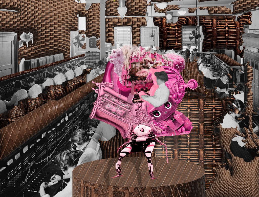
Pink-Collar Work Burnout.
[D1], [I17] Images made by AI Midjourney Image Generator using prompts that are the headlines of media articles that highlight gender-bias and issues related to Diversity, Equity, and Inclusion in STEM fields.
This image was made using Midjourney AI Art Generator with the prompt created using the title of the article with the same name:
Prompt: “The Burnout Crisis in Pink-Collar Work Plus: A housing revolution is coming. By Isabel Fattal”
Link to the article: https://www.theatlantic.com/newsletters/archive/2022/10/the-burnout-crisis-in-pink-collar-work/671668/


occipital neuralgia fabric flying car swirl scrub pee sarah lucas josephine cochrane 1838-1913 porch neighbor bobcat hysterectomy fork ocean messy fuddy-duddy
[F1], [B17], [C17] Images made using nonsensical prompts that are output from my !!! techn010ffspring !!! idea generator and then input as absurd combinations of words for AI Midjourney Image Generator to grapple with, in order to confound the AI in a refusal of its training, or an absurdity-detraining.
This image was made using the AI Art Generator Midjourney by entering the prompt created by my !!! techn010ffspring !!! idea generator.
The idea generator can be found at the link: https://openprocessing.org/sketch/1635641
The prompt entered was:”occipital neuralgia, fabric, flying car, swirl, scrub, pee, sarah lucas, josephine cochrane, 1838-1913, porch, neighbor, bobcat, hysterectomy, fork, ocean, messy, fuddy-duddy”

numbness bed truck pat smell bobcat co-worker loaf of bread wind office julie mehretu josephine cochrane (1839-1910) lumpectomy colon gush smoosh doily
[F1], [B17], [C17] Images made using nonsensical prompts that are output from my !!! techn010ffspring !!! idea generator and then input as absurd combinations of words for AI Midjourney Image Generator to grapple with, in order to confound the AI in a refusal of its training, or an absurdity-detraining.
This image was made using the AI Art Generator Midjourney by entering the prompt created by my !!! techn010ffspring !!! idea generator.
The idea generator can be found at the link: https://openprocessing.org/sketch/1635641
The prompt entered was: “numbness bed truck pat smell bobcat co-worker loaf of bread wind office julie mehretu josephine cochrane (1839-1910) lumpectomy colon gush smoosh doily”
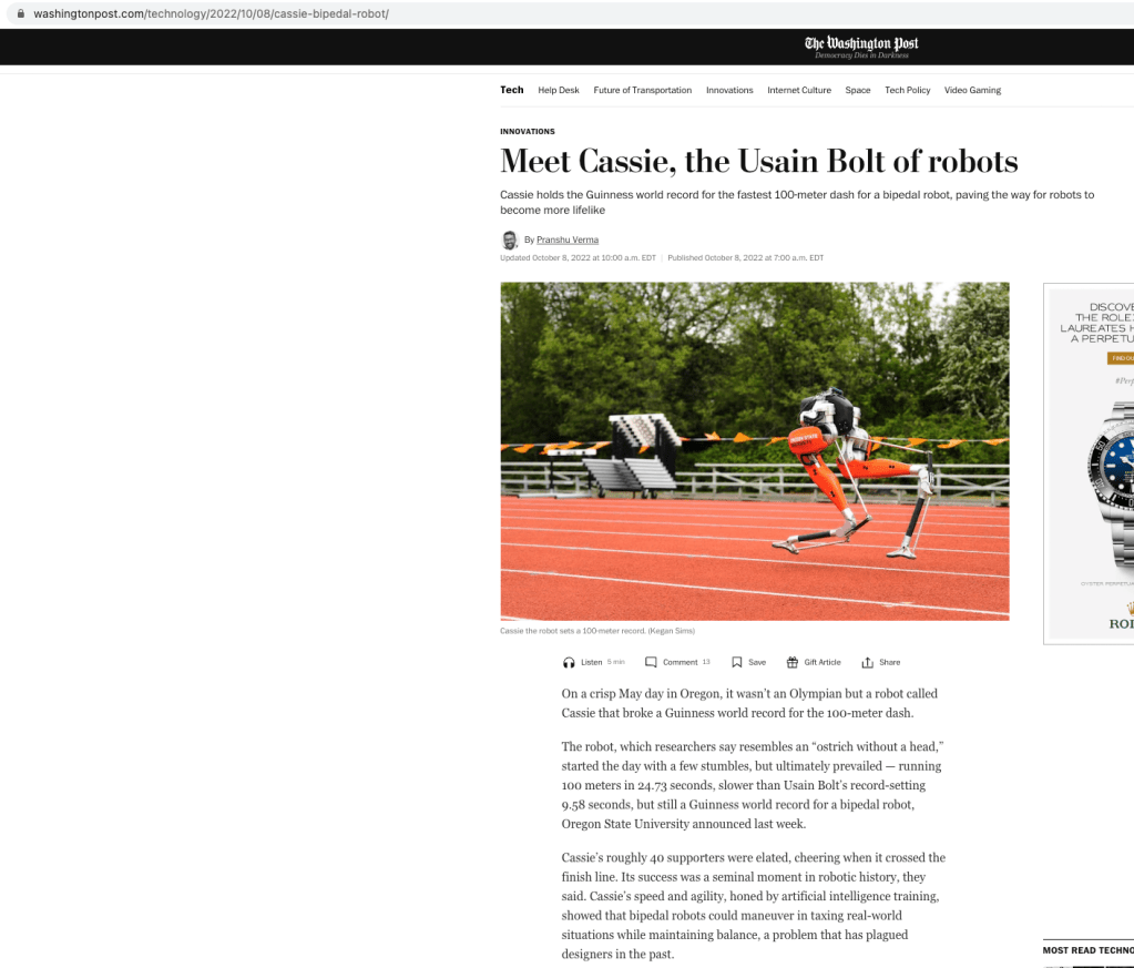
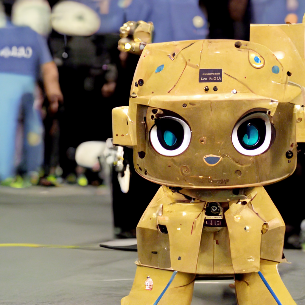
Cassie, Running Robot.
[D1], [I17] Images made by AI Midjourney Image Generator using prompts that are the headlines of media articles that highlight gender-bias and issues related to Diversity, Equity, and Inclusion in STEM fields.
This image was made using Midjourney AI Art Generator with the prompt created using the title of the article with the same name:
Prompt: “Meet Cassie, the Usain Bolt of robots Cassie holds the Guinness world record for fastest 100 meter dash for a bipedal robot, paving the way for robots to become more lifelike”
Link to article: https://www.washingtonpost.com/technology/2022/10/08/cassie-bipedal-robot/
constipation bed flying car upside down clean fennec fox father jello kiki smith porch dirt hedy lamarr (1914-2000) uterus placental abruptions smooshy lollygag
[F1], [B17], [C17] Images made using nonsensical prompts that are output from my !!! techn010ffspring !!! idea generator and then input as absurd combinations of words for AI Midjourney Image Generator to grapple with, in order to confound the AI in a refusal of its training, or an absurdity-detraining.
This image was made using the AI Art Generator Midjourney by entering the prompt created by my !!! techn010ffspring !!! idea generator.
The idea generator can be found at the link: https://openprocessing.org/sketch/1635641
The prompt entered was: “constipation bed flying car upside down clean fennec fox father jello kiki smith porch dirt hedy lamarr (1914-2000) uterus placental abruptions smooshy lollygag”
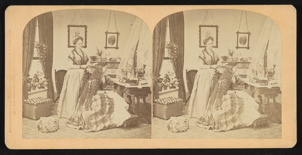
[Woman standing behind a girl and braiding her hair]
Title ● [Woman standing behind a girl and braiding her hair]. ● Created / Published: 1872.
Library of Congress. ● https://www.loc.gov/item/2022651339/
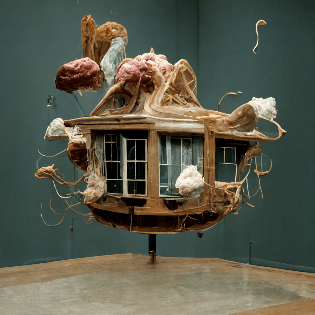
Self-cleaning building construction, with self-cleaning and drying clothes closet
[G1] Frances G. Bateson ● Patent #US4428085A ● Patented January 31, 1984 ● “Self-cleaning building construction” ● “According to the present invention, a self-cleaning building construction, including walls, ceiling and floor defining an enclosure, is provided with means for automatically or semi-automatically cleaning the same. Water distribution means are located proximate the ceiling of the enclosure and are adapted to deliver a spray of water or mist to the interior of the enclosure, with the enclosure floor sloping toward a drain for moisture removal. Air delivery means provide movement of air into the enclosure for drying the surfaces after washing. Although water alone may be employed in the washing cycle, a mixture of water and detergent is preferred, followed by rinsing and drying.”
“A self-cleaning building construction comprises apparatus for applying a fine spray or mist of water and/or water and detergent to wall, floor and ceiling surfaces, followed by warm air drying. Floors slope in a direction for removing excess moisture via a drain. Also included are closet apparatus for cleaning clothing, cupboard-dishwasher apparatus for cleaning stored dishes, self-cleaning bathtub apparatus, and self-cleaning washbasin apparatus.”
“
BACKGROUND OF THE INVENTION
The present invention relates to a building construction and apparatus characterized by ease of upkeep, and particularly to a building construction or apparatus wherein cleaning is mechanized and substantially automatic.
Although the average home or building is provided with various laborsaving devices, very little progress has been made toward automation of the basic cleaning of the building itself. Thus, cleaning of wall, floor and window surfaces as well as counter tops, table tops, plumbing appliances and the like involves a great deal of hand labor, with the basic cleaning functions consuming a considerable proportion of the average homemaker’s time. In addition, appreciable time is expended in the washing of clothing, dishes, and the like even with the aid of conventional apparatus designed for the purpose.”
“Referring to FIGS. 8 and 9, illustrating a clothes closet and clothes freshener according to the present invention, the clothes closet 76 comprises a first or outer chamber 170 accessible by exterior doors 172, and an interior chamber or clothes freshener 78 located at one longitudinal end of chamber 170. The clothes freshener chamber 78 is provided with insulated walls 174 and insulated doors 176 for keeping the heat of warmed water within the chamber. The inner wall of the chamber 78 is domed at 178 to receive a spray device 20′ extending downwardly from pipe 180 for delivering a spray or mist of water to the clothes freshener. A similar device 20′ extends upwardly from lower pipe 182 at the central bottom of the chamber surrounded by lower grillwork 184. The devices 20′ are substantially the same in construction and operation as the spray device 20 illustrated in FIG. 2 except that the devices 20′ are provided with spray nozzles only on one side as illustrated for directing moisture towards clothes 186 hanging from rod 188 in the chamber 78. The dome 178 at the top of the chamber is also constructed with a vent pipe 190 which is alternatively employed to supply drying air to the interior of the chamber. The interior of the chamber including the bottom thereof is waterproofed, being formed of fiberglass or having baked enamel metal wall construction, and includes a lower catch basin 192 for collecting water. The catch basin is disposed over a sloping subsupport 194, said subsupport positioning a sloping water drain floor 196-196′ in both chambers. An opening 198 along the lower wall between the two chambers allows runoff of excess water via floor 196′ to the opposite end of the first chamber and drain 200 or other water disposal course accessed through an opening 202 in the far end closet wall. For the saving of water, it is also possible to reuse the water in the lower catch basin portion of the clothes freshener chamber and recycle the same (by means not shown) through sprayer devices 20′. Grill 184 in the clothes freshener chamber also has its counterpart 184′ in the first or closet chamber such that any dripping may be collected from dampened clothes.
Clothes rod 188 extends the full length of both chambers through a half opening 204 in each of the doors 176 whereby the doors may be closed therearound during operation of the clothes freshener. A central slot of the top of the rod 188 is segmented as indicated at 206 for separating clothes hanging on hangers in the clothes freshener chamber to insure each item receives an adequate supply of moisture.
In use, the purpose of the clothes freshener device is not to wash and scrub clothing completely, but to freshen the same for rewearing without the necessity of excessive frequent washings. Clothing just worn may be placed in the clothes freshener, e.g. overnight for spraying and drying, after which the same is removed through opened doors 176 to the main portion of the closet. The doors 176 are closed when the clothes freshener is in use. The common rod 188 facilitates the movement of clothing from one compartment or chamber to the other. While both detergent and water may be used, followed by the use of water for rinsing in the clothes freshener, the use of warm water spray alone is preferred, followed by a drying cycle. The control of operation will be more completely described in connection with FIGS. 17, 23 and 24.”
patents.google.com/patent/US4428085A


typewriter spaceship tingling twist pick up wolf co-worker rainbow pee battery-powered cheerio salpingectomy wonkiness kara elizabeth walker beach mary sherman morgan (1921-) montage toothy dilly daly chest
[F1], [B17], [C17] Images made using nonsensical prompts that are output from my !!! techn010ffspring !!! idea generator and then input as absurd combinations of words for AI Midjourney Image Generator to grapple with, in order to confound the AI in a refusal of its training, or an absurdity-detraining.
This image was made using the AI Art Generator Midjourney by entering the prompt created by my !!! techn010ffspring !!! idea generator.
The idea generator can be found at the link: https://openprocessing.org/sketch/1635641
The prompt entered was: “typewriter spaceship tingling twist pick up wolf co-worker rainbow pee battery-powered cheerio salpingectomy wonkiness kara elizabeth walker beach mary sherman morgan (1921-) montage toothy dilly daly chest “
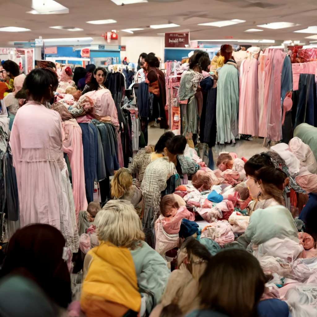
a melting pot of mixed up babies roils a horde of bargain hunting mothers when their local department store offers a “baby check” service on the day of a massive sale for infants’ wear.
[F1], [B17], [C17] Images made using nonsensical prompts that are output from my !!! techn010ffspring !!! idea generator and then input as absurd combinations of words for AI Midjourney Image Generator to grapple with, in order to confound the AI in a refusal of its training, or an absurdity-detraining.
This image was made using the AI Art Generator Midjourney by entering the prompt created by Copy.ai after entering in a name of one of the !!! techn010ffspring !!!. The prompt was: “a melting pot of mixed up babies roils a horde of bargain hunting mothers when their local department store offers a “baby check” service on the day of a massive sale for infants’ wear.”
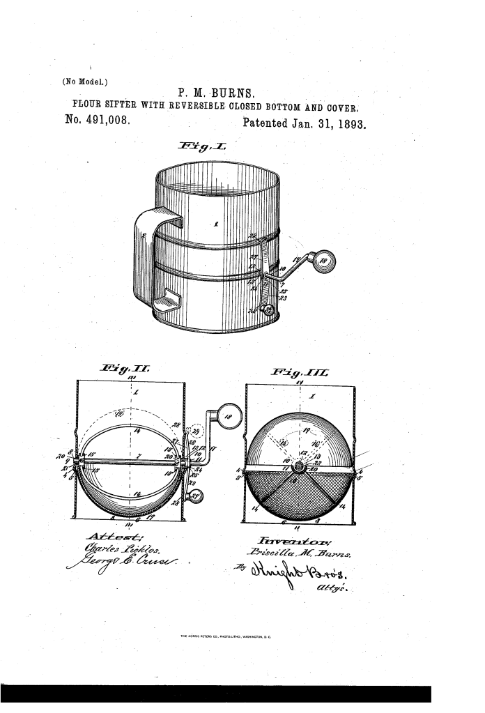
Flour-sifter with reversible closed bottom and cover.
[F17] Priscilla M. Burns ● Patent #US491008A ● Patented January 31, 1893 ● “Flour Sifter with Reversible Closed Bottom and Cover” ● “This invention relates to a rotary flour sifter, that has an alternating, semi-spheric tight bottom and cover, which in its bottom capacity, when not sifting securely retains the flour from escape, and which when said bottom is reversed in its elevated position when sifting, prevents the scattering of the flour by the sifter over the top of the sifter can.”
To all whom it may concern.-
ofthe city of St. Louis, in the State of Missouri, have invented a certain new and useful Improvement in Flour-Sifters with Reversible Closed Bottom and Cover, of which the following is a full, clear, and exact description, reference being had to the accompanying drawings, forming part of this specification.
This invention relates to a rotary flour sifter, that has an alternating, semi-spheric tight bottom and cover, which in its bottom capacity, when not sifting securely retains the flour from escape, and which when said bottom is reversed in its elevated position when sifting, prevents the scattering of the flour by the sifter over the top of the sifter can.
Figure I is a perspective view of thecan, and shows the sifter crank, and the rotatable arm with its hand knob, by which the semispheric alternating tight bottom and cover is inverted. Fig. II is a vertical section, taken on line 11-11, Fig. III, and shows in full lines the semi-spheric, alternating tight bottom and cover, adjusted into its lower position, for preventing the escape of the flour at the bottom of the apparatus previous to sifting, it also shows in broken lines, the said semi-spheric element in its elevated position in which it prevents the upward escape of the flour, while sifting; and Fig. III is a vertical section, partly in elevation, the section taken on line IIIIII, Fig. II and shows the semi-spheric alternating bottom and cover in its elevated position as a cover to prevent the upward escape of flour, while sifting.
Referring to the drawings:-1 represents the flour-can, which is of convenient form for scooping up the flour from the barrel or sack, when it is desired to replenish the same. 2 is the handle of said can.
3 represents a semi -spheric wire woven screen, whose upper peripheral edge 4 is seated within a circumferential groove 5 around the inside of said can, and is there secured by solder or otherwise. The bulge 6 of said semi-spheric screen lacks sufficiently from reaching on line with the bottom of the can,to prevent its coming in contact with the table, or any other flat object on which the sifter can is placed when at rest.
7 represents a crank-axle whose oif journal 8 Works inthe perforate bearing 9 in the far side of the can, and its nigh journal 10, has its tube bearing 11, in the sleeve 12, which sleeve has its perforate bearing 13, in the nigh side of the machine. l trepresents semi-circular beating wires, whose ends are fast seated in the sockets 15 in the collar hubs 16, which hubs are themselves fast seated on said crank axle 7, within close working distance inside said semi-spheric screen 3. 17 represents the crank on said axle 7, and 18 is the knob-handle by which said crank axle and the semispheric beaters are turned to agitate the flour, while sifting.
I now come to important elements of my device, which, in conjunction with the said sleeve 12, prevent the escape of the flour from the can when not sifting and which also by an alternatingchange of position prevents the u pward escape of the agitated cloud dust of flour from the top of the can while siftin 19 represents a semi-spheric, preferably metal cup, which has perforate projecting lugs 20 on each of its journal attached sides. The off side lug hasaloose bearing 21 on near the off end of the axle 7, and the nigh side lug has a tight bearing 22 on said sleeve 12.
23 represents a crank handle arm, which is fast mounted on the sleeve 12, to which sleeveit is rigidly secured by the key pin 24, which pin is seated in the key-hole 25 in said crank arm and sleeve, and thus locks them together. 26 represents a counter extension arm, integral with said crank arm 23, and which extends in the reverse direction to said crank handle end. The said combined crank handle and counter extension arm, is made of a concavoconvex form, its concave side 27 facing toward the flour-can, and the said facing side, at its ends has convex runner crooks 28, that as said arm attains its vertical position, exert a slight hold against the side of the can and hold it there. 29 is the knob handle on the operative end of said crank-arm 23, by which it is turned.
The operations of the especial devices in this apparatus that prevent the illegitimate escape of flour, when and where it is not required to be deposited in sifting, as an attachment to rotary flour sifters, are as follows:- The metal semi-spherical cup 19 having, by
means of one of its perforate lugs aloose bearing on the crank-axle 7, and its other perforate lug having a flat bearing on the sleeve 12 which sleeve has a loose bearing in said crank axle, and as the crank arm 23 is fast mounted and keyed on said sleeve 12, it follows that said crank arm is enabled to control the alternation in positionof said semi-spheric cup from that of a tight bottom, to prevent the escape of the flour, to the screen or sieve and from that its escape from the can, as shown in full lines in Fig. II, previous to starting the rotary sifter, on the one hand, to that of a tight cover, as shown in full lines in Fig. III, and in broken lines in Fig. II, to prevent the discharge of fine particles of the flour from the top, consequent on the agitation of sifting. The peripheral rim of said semispheric cup, approximately fits inside the flour-can, so that although it has free action in alternating, yet it substantially presents an efiective stay against the illegitimate escape of the’fiour. It’will further be seen, that when said crank arm 23 is turning said semi-spheric cup, to alternate it from a tight bottom to a tight cover, and vice versa, the convex runner crooks 28 of said arm and of its counter extension, do not come in contact with the flour can, until said cup reaches either its location as a tight bottom, (see Fig. II) or on the other hand, its position as a tight cover, (see Fig. 111,) at which time said convex crooks come in contact with the can and friction-lock the cup in either of its alternate locations.
– The sleeve 12 may be square seated in the crank arm 23, and tightened thereon when so required.
I claim as my invention:-
1. In a flour sitter, the combination of the can, the adjustable axially mounted revoluble hemispherical cup 19, free to oscillate back and forth and conforming to the interior of the can and the crank arm 23, by which said cup is alternated to effect respectively a tight bottom and cover; substantially as described.-
2. In a flour sitter, the combination of the semi-spheric cup 19, the can 1, within which said cup is axially mounted, the’cornbined crank arm 23 and counter extension 26, hav
ing the friction runner crooks 28, the said crank arm arranged to transpose said cup into its alternate positions to effect respectively a tight bottom and top, and said runner crooks 28, friction-locking said cup in said respective operating positions; substantially as described.
3. In a flour s’ifter, the combination of the flour can, the crank axle 7, the wire screen, the rotary heaters fast mounted on said axle, the sleeve 12 loosely mounted on said axle, the alternating cup 19 loosely mounted on said axle and fast mounted on said sleeve, and the crank arm 23 fast mounted on said sleeve; substantially as described.
4. In a flour sifter, the combination of the can 1, the crank axle 7, having its crank 17, the wire screen 3, the rotating heaters, 14, the sleeve 12 loosely mounted on said axle, the
semi-spheric cup 19, loosely mounted on said
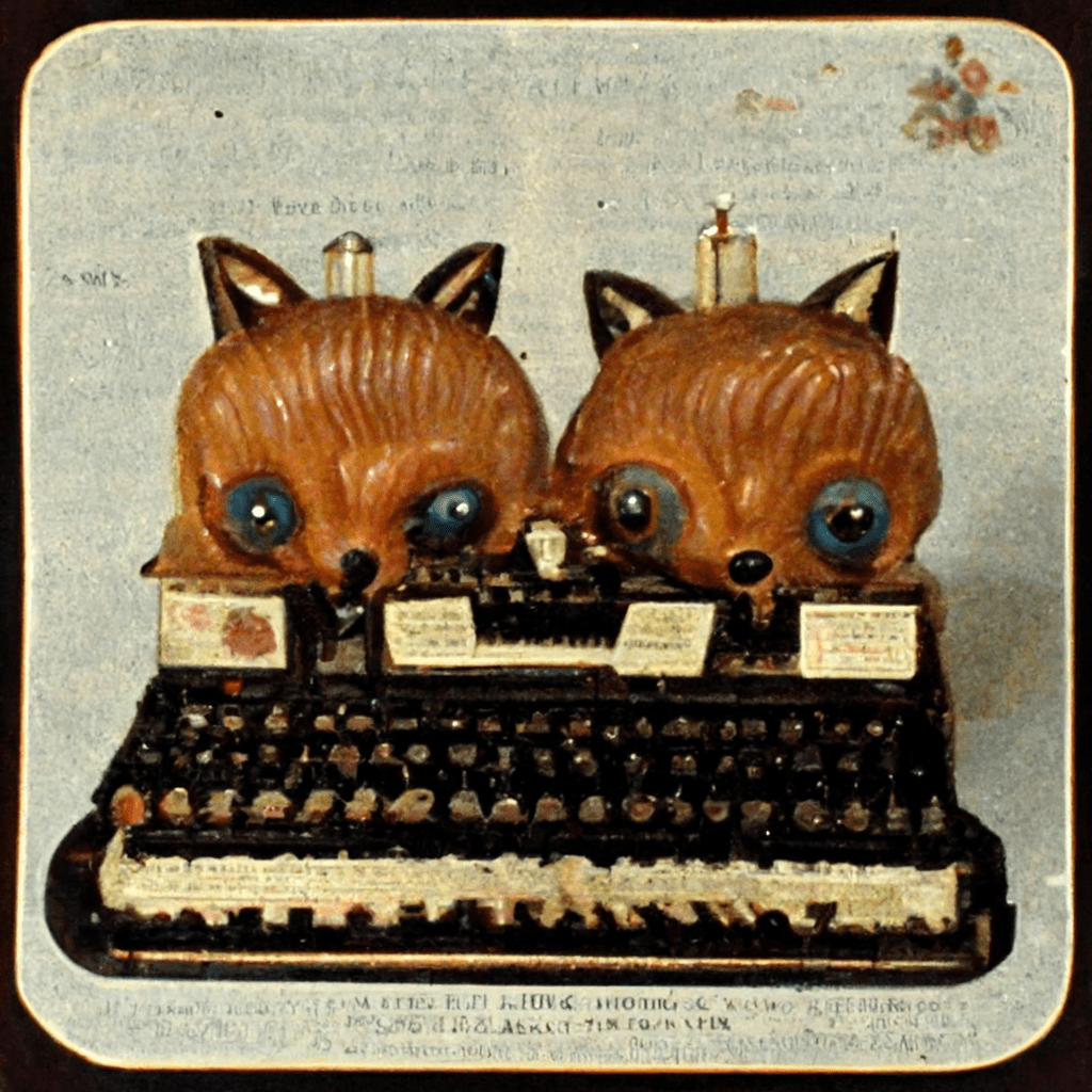
Tingling, the typewriter computer bit into the squirrel sister’s ear wax cake and held it fast. The sun in the family room seemed to illuminate Sue Williams, who was flummoxed by her identical twins.
[F1], [B17], [C17] Images made using nonsensical prompts that are output from my !!! techn010ffspring !!! idea generator and then input as absurd combinations of words for AI Midjourney Image Generator to grapple with, in order to confound the AI in a refusal of its training, or an absurdity-detraining.
This image was made using the AI Art Generator Midjourney by entering the prompt (which is the text for the narrative for !!! techn010ffspring !!! [v.9] : “Tingling, the typewriter computer bit into the squirrel sister’s ear wax cake and held it fast. The sun in the family room seemed to illuminate Sue Williams, who was flummoxed by her identical twins.”


Margaret-p-golvin-to-pound-clothes-with-insect-in-hair-scurrying-onto-antimicrobial-seat-cover-with-bearings-for-sale
[F1], [B17], [C17] Images made using nonsensical prompts that are output from my !!! techn010ffspring !!! idea generator and then input as absurd combinations of words for AI Midjourney Image Generator to grapple with, in order to confound the AI in a refusal of its training, or an absurdity-detraining.
This image was made using the AI Art Generator Midjourney by entering the name of one of the !!! techn010ffspring !!! as the prompt. The prompt was “Margaret-p-golvin-to-pound-clothes-with-insect-in-hair-scurrying-onto-antimicrobial-seat-cover-with-bearings-for-sale”.
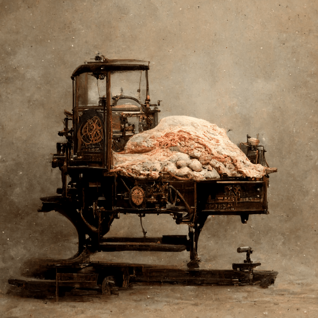
Multicopy attachment for typewriting machines
[G17] Beulah Louise Henry ● Patent #US2634849A ● Patented November 8, 1949 ● “MultiCopy Attachment for Typewriting Machines” ● “The invention has in view a multicopy attachment providing an ink impregnated supplemental ribbon which is adapted to be interposed between sheets of paper arranged in a typewriting machine with the supplemental ribbon disposed in parallel relation with the typewriter ribbon for producing ink impressions on the sheets for responding to the type impression on the original copy.”
“This invention relates to attachments for typ writing machines for simultaneously producing a plurality of ink copies.
The invention has in view a multicopy attachment providing an ink impregnated supplemental ribbon which is adapted to be interposed between sheets of paper arranged in a typewriting machine with the supplemental ribbon disposed in parallel relation with the typewriter ribbon for producing ink impressions on the sheets cor responding to the type impression on the original copy.
Another object of the invention is to provide a multicopy attachment of said character which is constructed and arranged for swingin movement to dispose the supplemental ribbon in operative position in parallel relation with the typewriter ribbon or in an outof-the-way inoperative position at one side of the typewriter to permit of the convenient insertion of the sheets of pap in the typewriter.
Another object of the invention is t provide means for the supplemental ribbon which normally spaces the ribbon from the sheets of paper so as to prevent smudging contact of the ribbon therewith and which engages the paper only when the type strikes the typewriter ribbon.
Another object of the invention is to provide means for spreading the ribbon guide means apart with the movement of the attachment into the out-of-the-way inoperative position and for moving the said guide means into close relation with the swinging movement of the attachment into operative position.
Another object of the invention is to provide a multicopy attachment of said character in which the supplemental ribbon is moved longitudinally within the guide means with the movement of the typewriter carriage from left to right for presenting different portions of the ribbon in position for producing the type impression on the paper.
Another object of the invention is to provide means for automatically reversing the direction of movement of the supplemental ribbon in the guide means for winding one end thereof on a spool and unwinding the opposite end thereof from another spool and vice versa.
Another object of th invention is to provide ribbon guide meansin the form of channels having longitudinally extending rectangular openings in the opposite faces thereof for engagement of the supplemental ribbon against the sheets of paper for receiving the typ impression thereon.
Still another object of the invention is to Pro vide an attachment of said character which can be conveniently applied to and removed from any standard typewriting machine.
With the foregoing and other objects in view. reference is now made to the following specification and accompanying drawings in which the preferred embodiment of the invention is mus– trated.”


Laundry-Related Patents
https://patents.google.com/patent/US1376942A
https://patents.google.com/patent/US1285731A
https://patents.google.com/patent/US630183A
https://patents.google.com/patent/US1530793A
https://patents.google.com/patent/US1559988A
https://patents.google.com/patent/US1752687A

Dough-Related Patents
https://patents.google.com/patent/US1212040A
https://patents.google.com/patent/US1296387A
https://patents.google.com/patent/US2205842A
https://patents.google.com/patent/US1642804A
https://patents.google.com/patent/US877675A
https://patents.google.com/patent/US1183314A
https://patents.google.com/patent/US1088070A
https://patents.google.com/patent/US702248A
https://patents.google.com/patent/US1814485A
https://patents.google.com/patent/US2616376A
https://patents.google.com/patent/US1825535A
